Table of Contents
RFD 868+ telemetry radio mount
Author: Friedrich Beckmann
The modem is connected to the PixRacer Telem2 port and the power module. The modem is mounted in the right fuselage half and will be connected just shortly before glueing the two fuselage parts to the PixRacer and the Powermodule.
UART cable to PixRacer
- Use three 12inch precrimped JST-GH cables
- Remove the JST-GH crimp at one side
- Remove 3-4mm of isolation to crimp a Harwin M20 crimp
- Crimp a Harwin M20 connector
- Use a Harwin 8 pin connector and put the crimps in the connector according to the following image

Compare the connector to the RFD868+ connections at the modem.

Remove Pin 15 of the RFD868+ modem. This will be the safety pin to avoid wrong mounting of the connector.

Solder the pin in a Harwin M20 connector and insert that connector in the Harwin housing. Fill the other four open places with empty Harwin M20 connector to increase the holding force of the connector.
Mark the RX and TX and GND cables and then weave the cables such that they are closer together. Now take a JST-GH 6-Pin connector and insert the pins according to this image

Pixracer pin layout: https://docs.px4.io/v1.9.0/assets/flight_controller/pixracer/grau_setup_pixracer_top.jpg Please note the different directions of the connector/cables in the labeling.
Pin layout of the Pixracer

Pin layout to the RFD868+

Note the difference between the yellow cable named TX on the board and RX on the connector!!! The name RX for the yellow cable on the JST-GH cable connector refers to the RX on the RFD868 modem. Please remember to connect the RFD868+ TX to the PixRacer RX and vice versa. So according to the following table:
| PixRacer JST-GH board | RFD868+ IDC connector |
|---|---|
| GND | GND |
| RX | TX |
| TX | RX |
The electrical connections of the cable are shown here:

The final weaved cable looks like this:

You can remove the cable markings.
Power Module to RFD868+ modem cable
- 4x 8“ JST already crimped cable
- JST 4-pin to female connector 8-pin
- GND + GND, 5V + 5V (double cable)
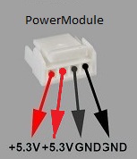
To mark the cable use colored shrink tube.