Table of Contents
Wing servo connection
The wings contain the servos for the aileron control. The wings must be detachable, i.e. it is not possible to have a permanent servo cable connection.
Components
- Tensility M5 3-pin plug, IP67, AWG26 (0.14mm2), 2.94€
- Tensility M5 3-pin socket, IP67, AWG26 (0.14mm2), 3.04€
Build instructions: M5 to Pixracer Cable
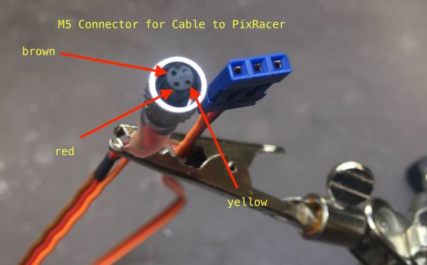
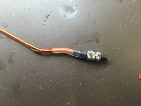
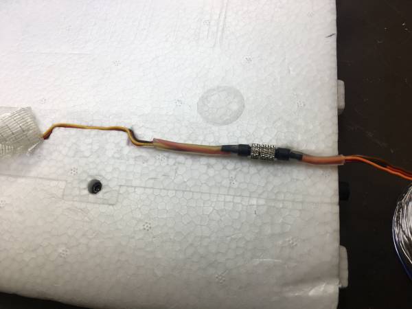
The following image shows the final cable from the M5 Connector to the PixRacer. This cable is equipped with the socket connector - the plug is attached to the cable from the servo.
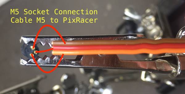
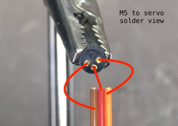
The next image shows the solder view of the socket connector. The yellow cable has to be on the left side.
- Shorten the servo cable by 40mm
- Cut 20mm of the transparent shrinking tube and put it on the cable
- Separate the yellow, red and brown cable for about 5cm
- Add about 5mm of the small shrinking tube to the red and the brown cable.
- Move the shrinking tubes as far as possible from the solder spot to avoid accidental shrinking
- Remove the isolation for about 4mm and twist and tin the wires.
- Put the plug and the socket together and fix the screws to avoid mechanical deformation due to the solder process
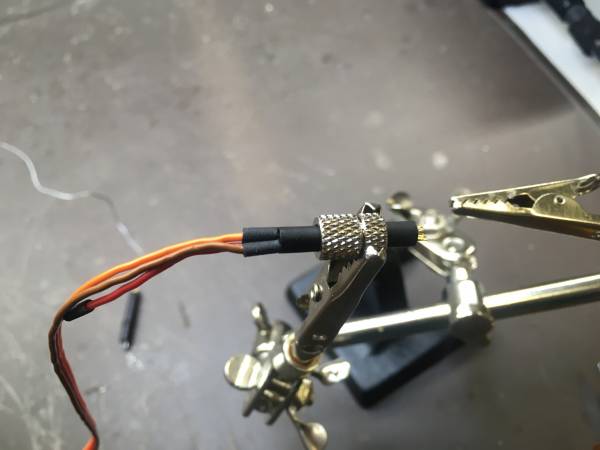
- Fix the socket with a helping hand.
- Solder the wire with a wide solder iron tip. Select a temperature of 250°C. Clean the solder tip with a wet sponge. Keep solder tin close to the setup. Hold the wire against the cup. Hold the tip against the solder wire to have a little bit of tin on the tip. Move the tip to the wire plus solder cup until everything melts. Then remove the solder tip. Hold the wire until everything is cooled.
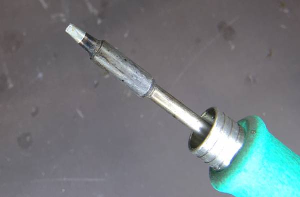
The next image shows the solder iron tip.
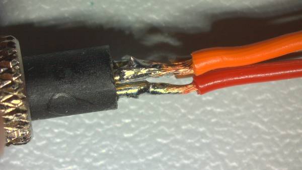
The next image shows the socket after the solder process.
And here with a closeup:
- Remove flux leftover with isopropanol and a brush (Pinsel).
- Move the small black shrinking tubes to the socket as close as possible
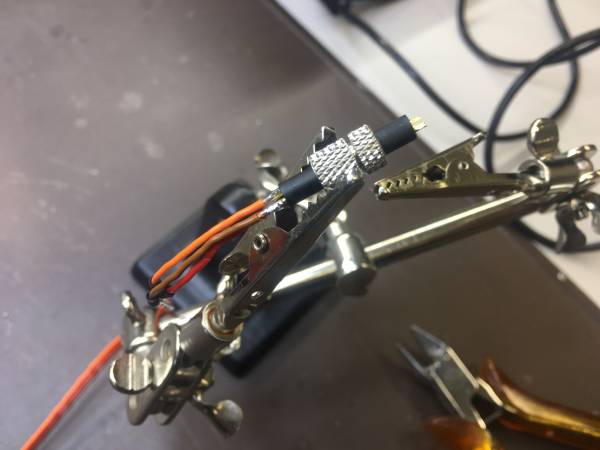
The next image shows the small shrinking tubes moved over the solder connections.
- Now shrink the black shrinking tubes with a heat gun. With the Heinel EL 1910 E heat gun select temperature “3” with maximum air speed.
- Move the 4mm/1mm transparent shrinking tube over the cable and the socket.
- Shrink with the heat gun with temperature “3” and make sure that the hot glue seals the cable and the socket.
- Make sure that the screw can still be turned after shrinking and cooling.
Done!
Build instructions: Servo to M5 cable
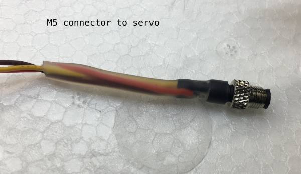
The next image shows the final M5 connector which is connected to the cable from the servo. This cable has the M5 “plug”. The M5 “socket” is on the cable to the PixRacer.
The flow is the same as for the M5 to Pixracer cable, but the 4mm/1mm shrinking tube should be 40mm long. The next image shows the cable connection from the solder view. The yellow cable is on the right side.
